Category Archives: STA Swing Type Torque & Angle Transducer

STA Swing Type Torque & Angle Transducer

STA (RF version)-Torque & Angle Control

STA (RF version)-Torque & Angle Control

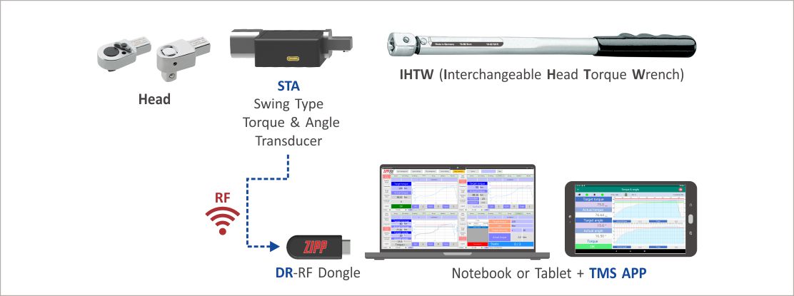
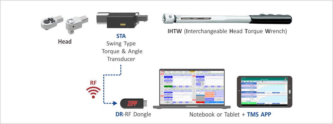
What are required

ZIPPTORK 020 1 System Architecture

ZIPPTORK 020 2

Procedures

  1. Insert Dongle into Notebook or Tablet.
  2. Open the TMS software.
  3. Set Dongle port.
  4. Enter the STA mode and then press the “Setup” button to enter the “Setup” page.
  5. Select the combination code.
  6. Please follow the combination shown in the tool combination code to complete the tool combination (headset with STA and interchangeable head torque wrench) in order.
  7. Turn on the STA transducer power.
  8. Select the STA transducer you want to use (the same tool combination setting is required).
  9. Select the working mode <Torque + Angle>.
  10. Set the inspection conditions and accuracy.
  11. Return to the work page.
  12. Set the initial target torque.
  13. Set the final target torque.
  14. Set the target angle.
  15. Start bolting.
  16. Release the STA after bolting to the target torque prompted by the system.
  17. Start bolting again and release STA after reaching the target angle.
  18. QC judgment.
  19. The system completes the work record (operator ID, date & time, target torque, actual torque, QC result and tool combination code).

STA (RF version)-Torque & Angle Calibration

STA (RF version)-Torque & Angle Calibration

What are required

ZIPPTORK 018 1 System Architecture

ZIPPTORK 018 2

Procedures

  1. Assemble the HEAD with STA & Interchangeable Head Torque Wrench.
  2. Insert the two Dongles into the NB separately.
  3. Open TMS APP software.
  4. Set up the TTA Dongle & STA Dongle ports respectively.
  5. Complete the pairing of TTA and STA respectively, after setting, turn on the TTA and STA.
  6. Continue to press the “Torque Correction” button to enter the “Torque Correction” page.
  7. Select the STA mode in TMS APP to enter the setting page and select the STA model you want to use.
  8. In TMS APP, select STA mode to enter the setting page and select the TTA model you want to use.
  9. Press the “Add” button and enter the tool combination number & name, Head number and torque wrench number The system automatically catches the STA number in the connection.
  10. Set the target torque.
  11. Insert the assembled STA wrench into the TTA, then continue to attach the socket and start to tighten the bolt.
  12. Stop tightening when the TTA indicates that the target torque has been reached.
  13. The system automatically fills the static torque value of TTA and STA into the corresponding form field in the software to complete the torque calibration.
  14. After the system completes the correction of the torque value, the operator needs to measure the length of the torque arm and fill in the angle parameter, then press the “Save” button to complete the angle calibration.

STA (RF version)-Residual Torque Verification

STA (RF version)-Residual Torque Verification

What are required
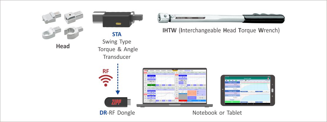
ZIPPTORK 021 1 System Architecture

ZIPPTORK 021 2

Procedures

  1. Insert Dongle into NB or Tablet.
  2. Open the TMS software.
  3. Set the Dongle port.
  4. Enter the STA mode and then press the “Setup” button to enter the “Setup” page.
  5. Select the combination code.
  6. Follow the combination shown in the tool combination code to complete the tool combination (head with STA and the wrench )
  7. Turn on the STA transducer.
  8. Select the STA transducer you want to use (To be the same tool combination setting).
  9. Select the working mode <Torque Verification>.
  10. Set the inspection conditions and accuracy.
  11. Return to work page.
  12. Set the target torque.
  13. Set the target angle.
  14. Start inspection.
  15. Loosen the STA after tightening to the target angle prompted by the system.
  16. QC judgment.
  17. System complete with work record (operator ID, date & time target torque, actual torque, inspection conditions & accuracy and tool combination code).

STA (RF version)-Torque Control

STA (RF version)-Torque Control

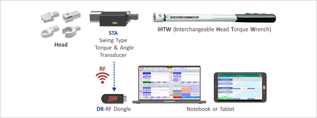
What are required

ZIPPTORK 019 1 System Architecture

ZIPPTORK 019 2

Procedures

  1. Insert Dongle into Notebook or Tablet.
  2. Open the TMS software.
  3. Set Dongle port.
  4. Enter the STA mode and then press the “Setup” button to enter the “Setup” page.
  5. Select the combination code.
  6. Please follow the combination shown in the tool combination code to complete the assembly (head with STA and interchangeable head wrench ) in order.
  7. Turn on the STA transducer power.
  8. Select the STA transducer you want to use (should be the same as the tool combination setting ).
  9. Select the working mode <torque>.
  10. Set the inspection conditions and accuracy.
  11. Return to the work page.
  12. Set the final target torque.
  13. Start bolting.
  14. Release the STA after bolting to the target torque prompted by the system.
  15. QC judgment.
  16. System complete on work record (operator ID, date & time, target torque, actual torque, accuracy and tool combination code).
This site uses cookies to offer you a better browsing experience. By browsing this website, you agree to our use of cookies.