Author Archives: ZIPP GROUP

ZIPPTORK Bolting Technology

ZIPPTORK 035 1

ZIPPTORK Bolting Technology

Bolt Load Control of Threaded Fasteners

In order to meet the industrial development trend of Industry 4.0, our company has introduced a full range of patented products related to bolt tightening technology, which provides a cost-effective solution for the industry. Bolting of threaded fasteners is affected by many factors, such as the softness of the material of the fasteners (bolts, nuts and washers) and the surface roughness of the fasteners to be tightened, the influence of bruises or oil contamination on the threads during the process, and the difference in the structure and quality of the tools used, all of which make it difficult to control accurately and effectively.

Furthermore, for the most important purpose of bolting works ~ the clamping force applied to the bolted joint, most of the industry can only control the clamping force of the bolt load by ultrasonic sensing & bolting technology. Some applications even require monitoring of the bolted joint status after bolted and real-time notification when abnormal conditions occur. For this purpose, ZIPPTORK has developed a series of bolt load control technologies to provide the ultimate solution for threaded fastener tightening works, fully meeting the requirements of the Industrial Internet of Things(IIoT) applications.

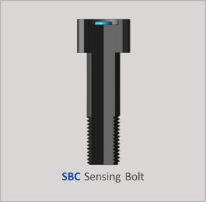
Sensing Bolt & patented anti-vibration Sensing Washer for bolt load control & monitoring
It is ideal for all kinds of bolt tightening operations that require precise control of the clamping force and monitoring the bolted joint status at any time, and the patented anti-loosening design and ease of use make it more advantageous than the conventional ultrasonic sensing & bolting technology in mainstream applications as a great cost-effective alternative.

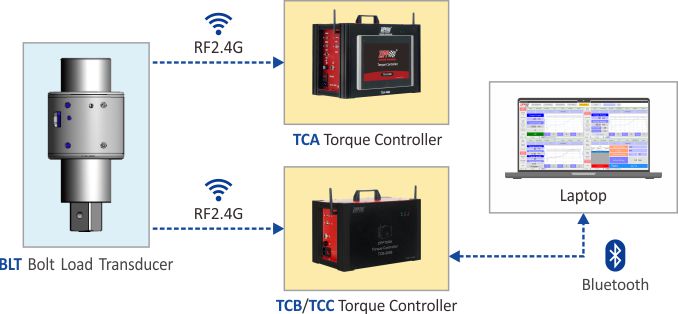
Patented Bolt Load Transducer
It can be used with any brand and type or design of manual, pneumatic or electric torque tools to directly control and display the corresponding clamping force generated on the bolted joint by the applied torque at the time, and can collect relevant data.It overturns the traditional method of controlling the bolting torque by torque tools, and directly measures the clamping force induced in the bolted joint instead, effectively improving the quality of bolting operations. A new era of “Bolt Load Wrench” is to come!

Ideal for critical bolted joints where bolt load control is important & bolted joint status monitoring is required
ZIPPTORK 035 1

The Ultimate Solution of Bolting Technology

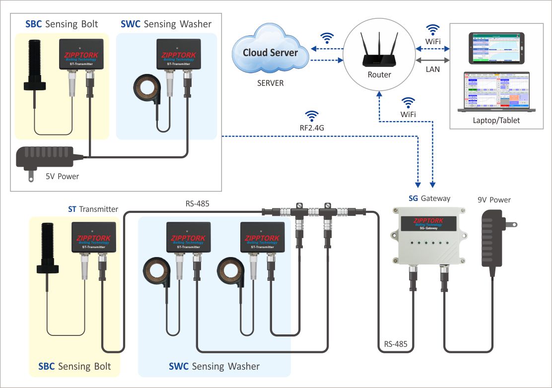
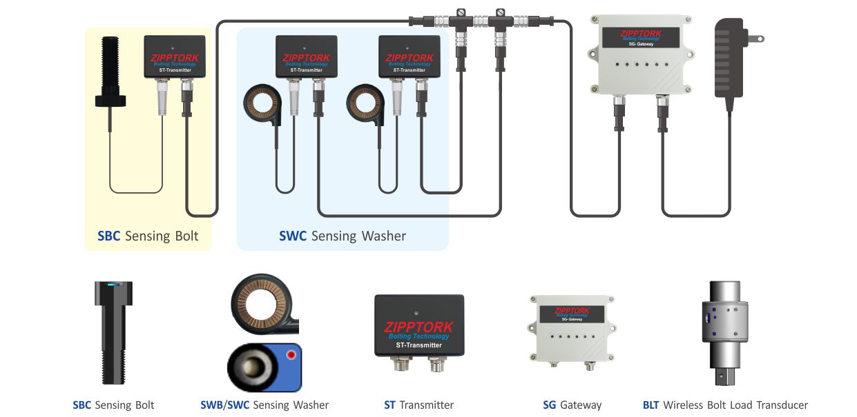
Sensing Washer with functions of anti-loosening for controlling bolt load and monitoring the bolted joint status

  • What is different from the past products or current market products?
    Currently, following methods are commonly used to test the clamping force in the market:

    • Ultrasonic inspection method – This inspection method is time-consuming, labor-intensive and expensive.
    • Wired sensor bolt – This test method is wired, difficult to achieve wirelessly, and expensive.
    • Load cell-This inspection method is wired, difficult to achieve wirelessly, and expensive.

The clamping force control is only for the sensor to connect to the PLC or other display device by wired, the layout of the bolt load sensor of these methods are laborious and time-consuming, and the clamping force sensor does not have any antiloosening design, and does not have the bolting sequence control function.

  • Our company has been in the field of pneumatic tools for more than 40 years, and has been dedicated to the research and development of bolting technology for decades.
    However, in the field of bolting operation, torque control is not the most accurate technology, but bolt load (clamping force) control is the ultimate and most accurate method; since the bolt load sensor is more expensive than the torque sensor, the market is still dominated by torque control. In recent years, customers’ demand for bolting work and data recording is getting higher and higher, and there is an urgent demand for clamping force control in the market, therefore, our company has spared no effort to innovate and breakthrough in research and development in order to make the best and ultimate clamping force control and monitoring for thread fasteners.
  • Due to the difficulty in mass production of the wireless bolt load sensor, the Sensing Bolt developed by our company at the beginning is hard to improve the yield rate and reduce the cost. With our efforts, we have finally developed a new generation of Sensing Washers to replace the Sensing Bolts, which have the following advantages:
    1. The Sensing Washer is suitable for both wireless communication and wired connection. The wireless Sensing Washer is suitable for small magnetic field interference fields – such as automotive industry, oil mining industry, etc.; the wired induction spacer is suitable for large magnetic field interference fields – such as construction and bridge industry, aerospace industry, etc.
    2. Low production cost and high yield rate
    3. Anti-loosening design (the sensing bolt itself does not have an anti-loosening design) – this anti-loosening design is patented. In practice, it is easy to carry, easy to install and easy to operate.
    4. Higher accuracy and stability than sensing bolts, with dynamic bolt load control accuracy of ±10% and static bolt load control accuracy of±5%.
    5. No need to use special or custom-made bolts, just use general bolts and sensing washers to achieve the following functions:
      During bolting process:
      a) The bolting sequence can be controlled with our innovative controller and tag.
      b) Bolt load control
      c) Torque equivalent for reference After bolted,
      combined with Industry 4.0-IoT:
      a) Bolted joint ( bolt load-clamping force) monitoring
      b) Torque equivalent display
      c) Clamping force, torque equivalent abnormal alarm
    6. Applicable tools: Any brand of manual, pneumatic and electric torque tools (static, impact, hydraulic pulse)
    7. Application: Construction, oil, mining, automotive, aerospace, etc., where clamping force monitoring is required.
    8. Applicable environment: High magnetic field interference environment, lightning strike environment…etc.
    9. The application can be used not only with our self-developed controller to achieve the clamping force and bolting sequence control, but also as a stand-alone device, the detailed application structure is attached.

ZIPPTORK Bolt Load Control & Monitoring

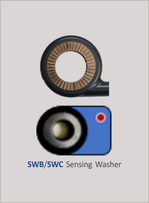
Anti-vibration Sensing Washer
ZIPPTORK 037 1
  • Patented anti-vibration design to ensure the best stability of the bolted joint.
  • Bolt axial load control during bolting process by any torque tool.
  • Bolt joint status such as bolt load, temperature and vibration variation remote monitoring.
  • The best alternative for transmission equipment preventive maintenance work.
  • Applicable to any axial load joint status monitoring including HUCK lock bolt.
  • Remote monitoring bolted joint periodically or continuously and alert as soon as reach the preset threshold.
  • The most economic yet effective alternative of ultrasonic bolting technologies.
  • SWBN/SWBR should be custom-made. Please contact Sales personnel.

Sensing Bolt

ZIPPTORK 037 2
  • Bolt axial load control during bolting process by any torque tool.
  • Bolt joint status such as bolt load, temperature and vibration variation remote monitoring.
  • The best alternative for transmission equipment preventive maintenance work.
  • Remote monitoring bolted joint periodically or continuously and alert as soon as reach the preset threshold.
  • The most economic yet effective alternative of ultrasonic bolting technologies.

ZIPPTORK Bolt Load Control Technology

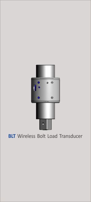
Wireless Bolt Load Transducer
ZIPPTORK 037 3

For sensing and controlling bolt load generated in
the bolted joint instantly throughout the bolting process

  • Patented design for direct sensing the bolt load induced on the joint during the bolting process.
  • With functions of data logging and up load to peripheral device or cloud server.
  • To be attached to the drive anvil of any type of torque tool for direct bolt load control.
  • Patented vibration proof design, also good for impact torque tools.
  • RF2.4G wireless transmission and data collection.

ZIPPTORK 037 4

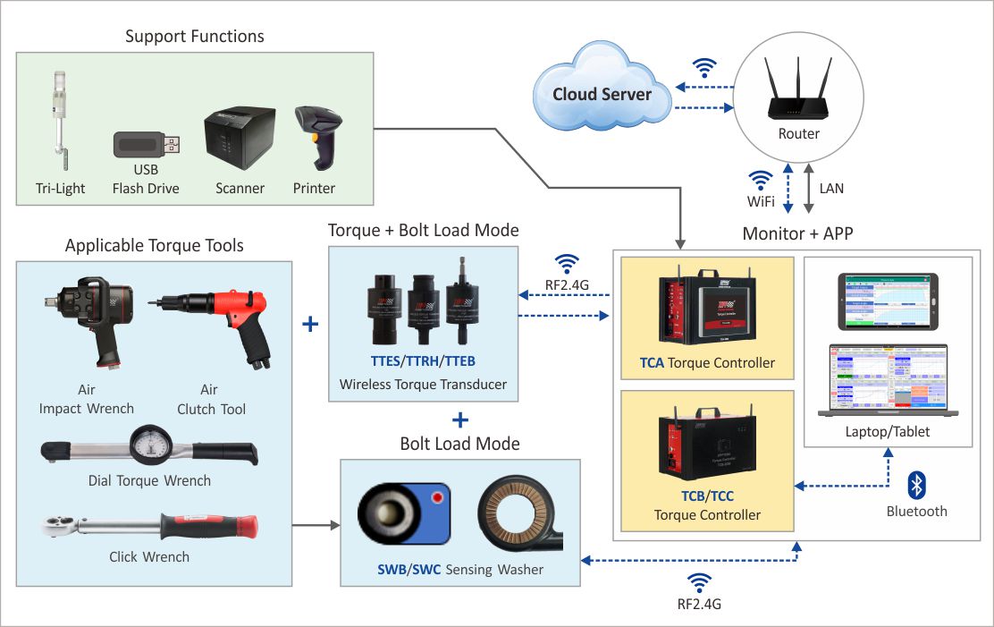
Bolt Load Control Products Application Embodiment

Bolt Load Control During Bolting Process
ZIPPTORK 038 1

Bolted Joint Status Monitoring

ZIPPTORK 038 2

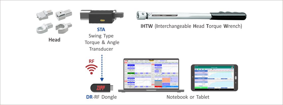
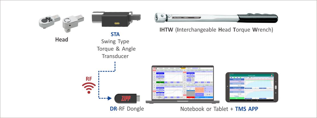
STA (RF version)-Residual Torque Verification

STA (RF version)-Residual Torque Verification

What are required

ZIPPTORK 021 1 System Architecture

ZIPPTORK 021 2

Procedures

  1. Insert Dongle into NB or Tablet.
  2. Open the TMS software.
  3. Set the Dongle port.
  4. Enter the STA mode and then press the “Setup” button to enter the “Setup” page.
  5. Select the combination code.
  6. Follow the combination shown in the tool combination code to complete the tool combination (head with STA and the wrench )
  7. Turn on the STA transducer.
  8. Select the STA transducer you want to use (To be the same tool combination setting).
  9. Select the working mode <Torque Verification>.
  10. Set the inspection conditions and accuracy.
  11. Return to work page.
  12. Set the target torque.
  13. Set the target angle.
  14. Start inspection.
  15. Loosen the STA after tightening to the target angle prompted by the system.
  16. QC judgment.
  17. System complete with work record (operator ID, date & time target torque, actual torque, inspection conditions & accuracy and tool combination code).

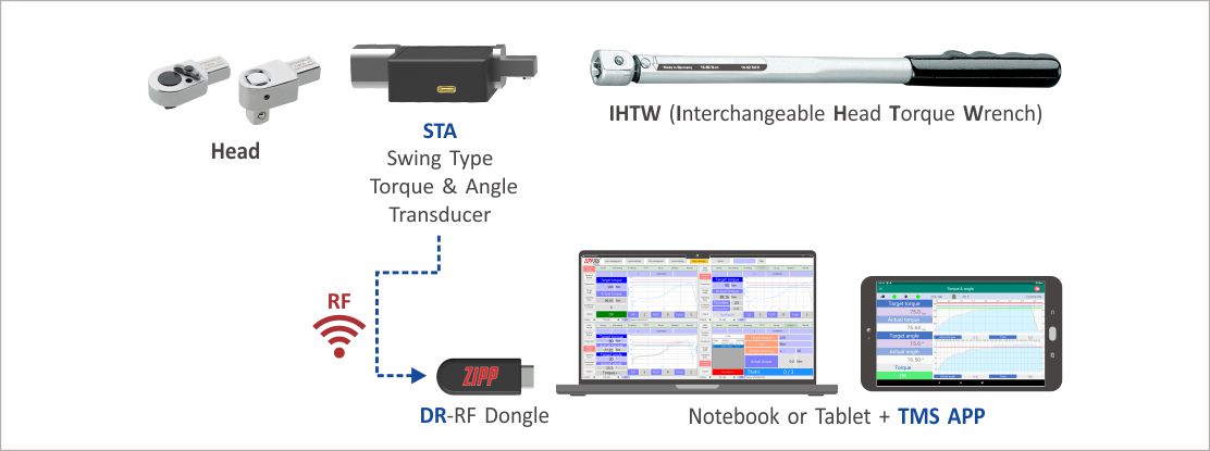
STA (RF version)-Torque & Angle Control

STA (RF version)-Torque & Angle Control

What are required

ZIPPTORK 020 1 System Architecture

ZIPPTORK 020 2

Procedures

  1. Insert Dongle into Notebook or Tablet.
  2. Open the TMS software.
  3. Set Dongle port.
  4. Enter the STA mode and then press the “Setup” button to enter the “Setup” page.
  5. Select the combination code.
  6. Please follow the combination shown in the tool combination code to complete the tool combination (headset with STA and interchangeable head torque wrench) in order.
  7. Turn on the STA transducer power.
  8. Select the STA transducer you want to use (the same tool combination setting is required).
  9. Select the working mode <Torque + Angle>.
  10. Set the inspection conditions and accuracy.
  11. Return to the work page.
  12. Set the initial target torque.
  13. Set the final target torque.
  14. Set the target angle.
  15. Start bolting.
  16. Release the STA after bolting to the target torque prompted by the system.
  17. Start bolting again and release STA after reaching the target angle.
  18. QC judgment.
  19. The system completes the work record (operator ID, date & time, target torque, actual torque, QC result and tool combination code).

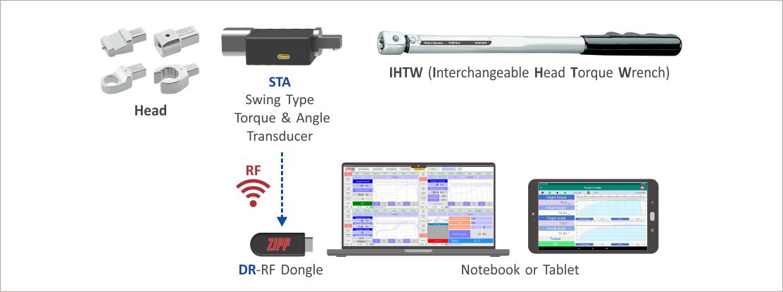
STA (RF version)-Torque Control

STA (RF version)-Torque Control

What are required

ZIPPTORK 019 1 System Architecture

ZIPPTORK 019 2

Procedures

  1. Insert Dongle into Notebook or Tablet.
  2. Open the TMS software.
  3. Set Dongle port.
  4. Enter the STA mode and then press the “Setup” button to enter the “Setup” page.
  5. Select the combination code.
  6. Please follow the combination shown in the tool combination code to complete the assembly (head with STA and interchangeable head wrench ) in order.
  7. Turn on the STA transducer power.
  8. Select the STA transducer you want to use (should be the same as the tool combination setting ).
  9. Select the working mode <torque>.
  10. Set the inspection conditions and accuracy.
  11. Return to the work page.
  12. Set the final target torque.
  13. Start bolting.
  14. Release the STA after bolting to the target torque prompted by the system.
  15. QC judgment.
  16. System complete on work record (operator ID, date & time, target torque, actual torque, accuracy and tool combination code).

STA (RF version)-Torque & Angle Calibration

STA (RF version)-Torque & Angle Calibration

What are required

ZIPPTORK 018 1 System Architecture

ZIPPTORK 018 2

Procedures

  1. Assemble the HEAD with STA & Interchangeable Head Torque Wrench.
  2. Insert the two Dongles into the NB separately.
  3. Open TMS APP software.
  4. Set up the TTA Dongle & STA Dongle ports respectively.
  5. Complete the pairing of TTA and STA respectively, after setting, turn on the TTA and STA.
  6. Continue to press the “Torque Correction” button to enter the “Torque Correction” page.
  7. Select the STA mode in TMS APP to enter the setting page and select the STA model you want to use.
  8. In TMS APP, select STA mode to enter the setting page and select the TTA model you want to use.
  9. Press the “Add” button and enter the tool combination number & name, Head number and torque wrench number The system automatically catches the STA number in the connection.
  10. Set the target torque.
  11. Insert the assembled STA wrench into the TTA, then continue to attach the socket and start to tighten the bolt.
  12. Stop tightening when the TTA indicates that the target torque has been reached.
  13. The system automatically fills the static torque value of TTA and STA into the corresponding form field in the software to complete the torque calibration.
  14. After the system completes the correction of the torque value, the operator needs to measure the length of the torque arm and fill in the angle parameter, then press the “Save” button to complete the angle calibration.
This site uses cookies to offer you a better browsing experience. By browsing this website, you agree to our use of cookies.